
This blog has a lot to do with Arduino, so we have to do a Blink project, right? Go fetch your Arduino Beginner’s kit and let’s get this over with…
What is Blink?
The “Blink” project is, traditionally, the very first project you’d make as an Arduino programmer. You may also want to run it again on any new development board you take out of the box. It basically makes a small light go on and off at a slow pace, and while it’s not a practical real-world application, a successful “Blink” does tell you two very important things:
- that your development toolchain, both software and hardware , is more or less operational
- that you managed to make that toolchain work, which may turn out to be quite a feat too.
What you’ll need
Software: The Arduino IDE (download from here). This usually installs without too much grief.
Hardware: A USB-connected Arduino board (Uno, Mega, or Duemilanove, other models can be used as well with very minor adjustments). Since my original Arduino is on loan (honest!), I’ll use a Duemilanove-compatible board here. We’ll discuss the issue of clones and compatibles in another post. Making the computer recognize the Arduino may prove to be a bit tricky; In case of trouble, Help yourself.
You’ll also need:
- A breadboard
- A standard, simple, cheap visible-light LED
- A resistor, with a value anywhere between 220 and 1000 Ohms
- Two solid-tip male-male jumper wires (Breadboarding Wires)
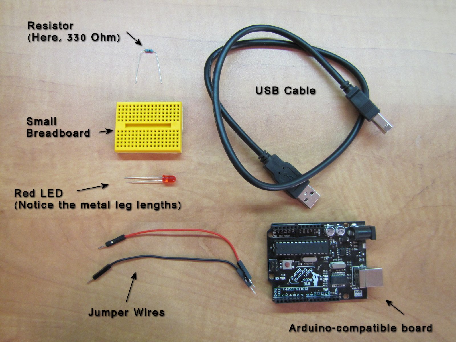
You can get these in any electronics shop, on eBay etc. If you don’t know what something in this list means, follow the links or check it out in this picture:
Let there be light
We’ll begin with a simple test to check just the hardware.
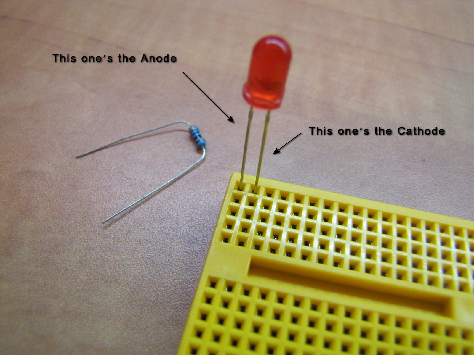
Take the LED and look at it. It should have one metal leg longer than the other. That’s the Anode, or “Plus”. Easy to remember, because plus means more, and it’s longer, get it?
The other, shorter metal leg is called the Cathode. These terms are important, because the LED will only emit light if connected correctly. So, take note of where the Anode is, and insert the LED with care into the breadboard, making sure each metal leg occupies a separate 5-hole row, like so:
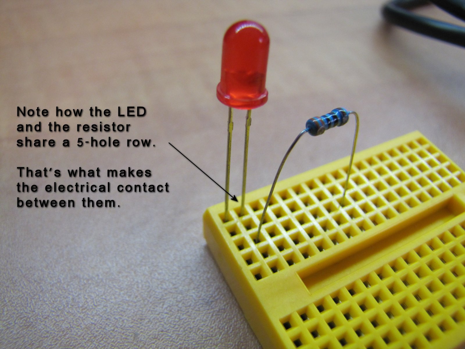
The resistor also has two legs, but it’s not directional so they are interchangeable. Insert one of them into the same 5-hole row as either the Cathode or the Anode of the LED. Insert the other into a different, third row. All five holes in each row are electrically connected to each other underneath. We need this resistor to limit the electrical current flowing through the components; otherwise, the LED will burn out and stink.
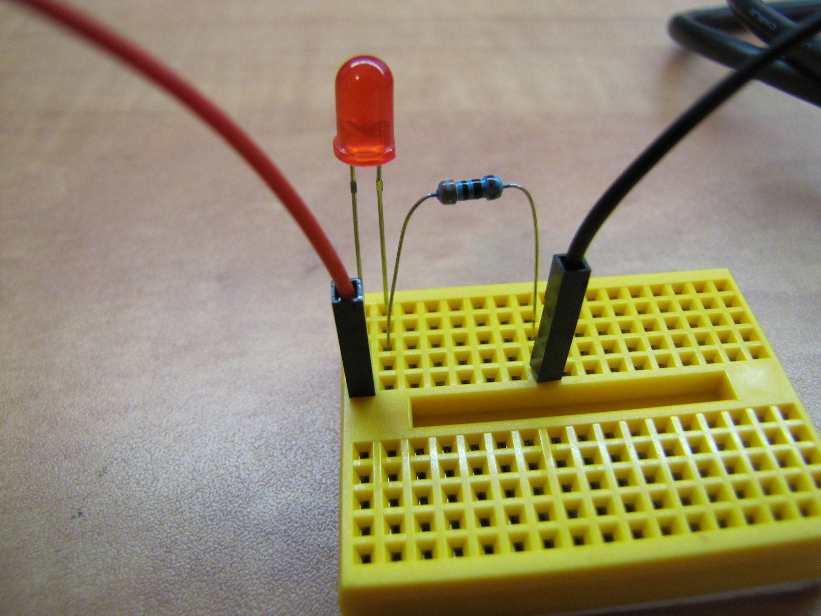
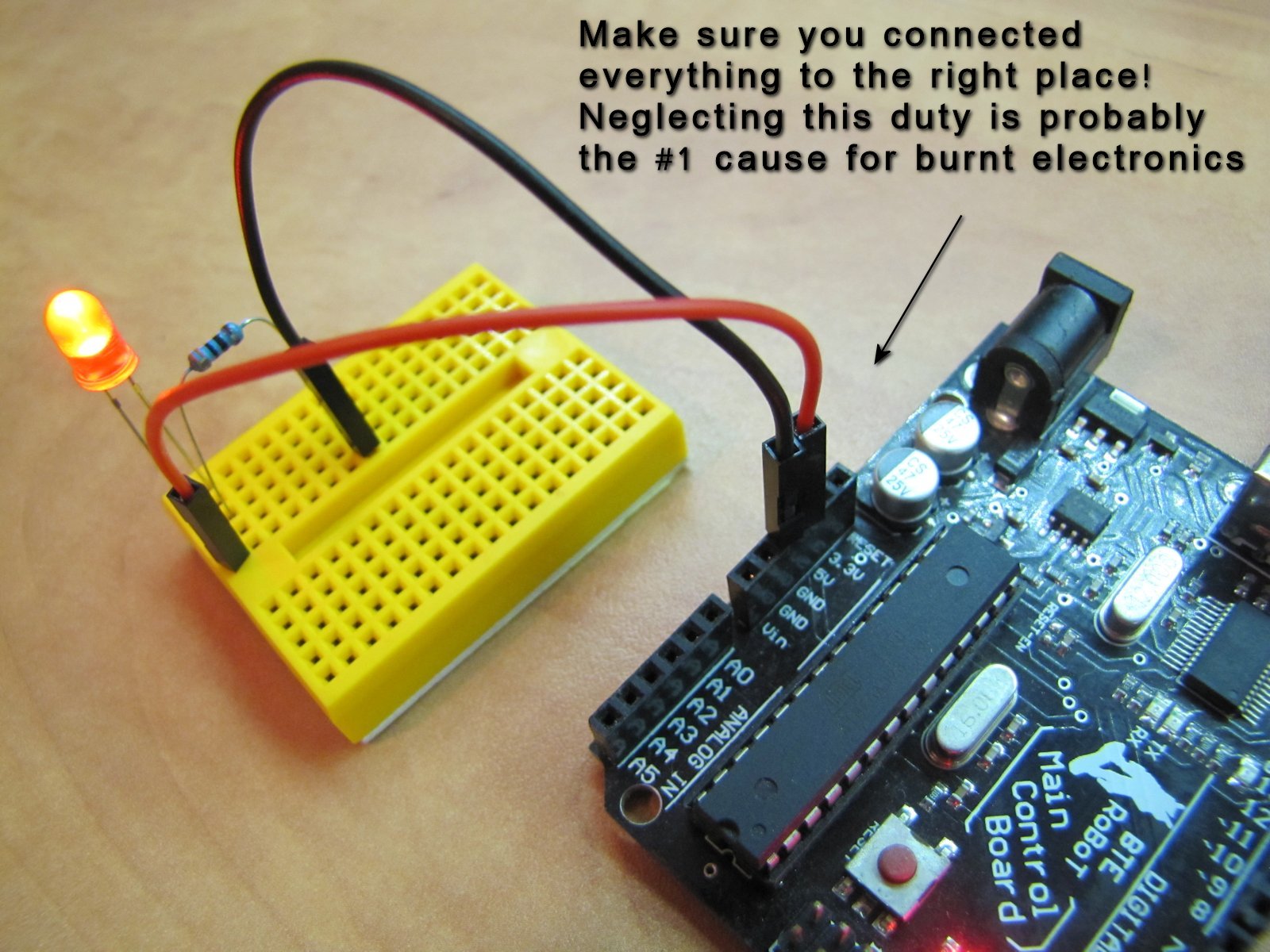
Attach jumper wires to the two rows that the LED and the resistor do NOT share. If you have any sense, use a red wire for the Anode side, and a black wire for the Cathode side. The colors won’t help the electricity flow, but sensible color-coding will save you infinite mixup problems in the future. You have been warned.
Now we’ll connect this circuit – yes, that’s what it’s called – to the Arduino. Don’t plug in the Arduino to the computer and don’t give it any power yet. Having loose wires around live electricity is another guarantee for disaster. So, take the free end of the red wire and plug it into the hole marked “5V” on the Arduino. Then plug the free end of the black wire into a hole marked “GND” (that’s “Ground”). You’ll find two GND holes near “5V” and another on the other side, near the hole marked “13”. By the way, these holes are counter-intuitively referred to as “pins”. That’s because they represent (and are directly connected to) the metal pins of the microcontroller.
Anyway, NOW you may power the Arduino. Did the LED light up?
If it didn’t light up, here’s what you may want to check:
- Are there any lit LEDs on the Arduino itself? If not, it means the Arduino doesn’t get proper power
- Did you mix up Anode and Cathode? Check again where each leg of the LED is connected.
- Did you miss a row on the breadboard? Remember that every component in the circuit has to “touch” another one, by being connected to the same row. Otherwise, the circuit is “open” (disconnected) and electricity can’t flow.
- Are all the connections solid? Wiggle the components and push them carefully down to make sure they have good contact.
Code time!
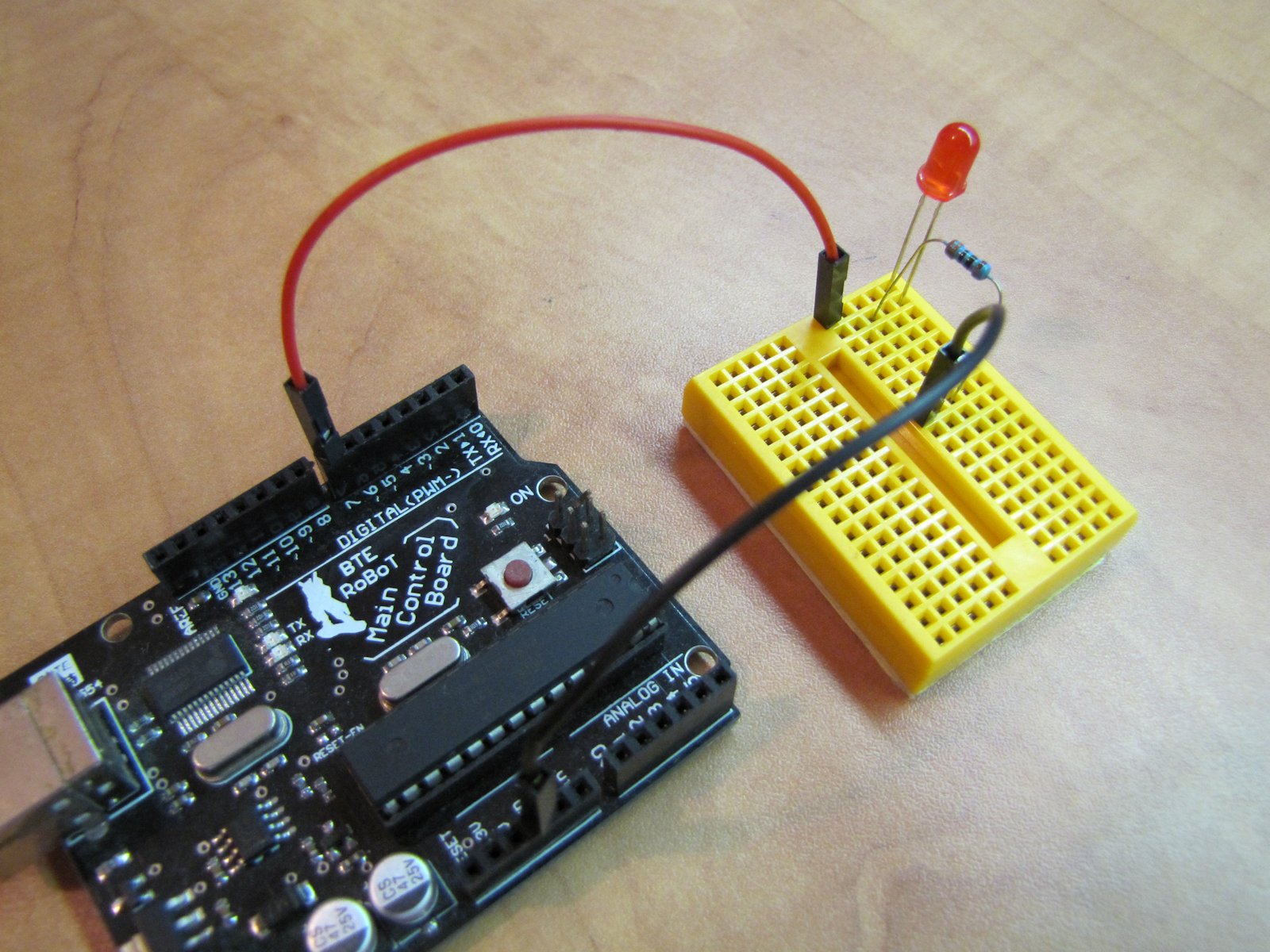
Power off the Arduino and disconnect the red wire from 5V. Instead, plug it into the Arduino pin marked “7”. Why that one? Because.
If you apply power now, the LED should remain unlit. That’s expected. Let’s fire up the Arduino IDE on the PC. As a default, it gives us these lines of code:
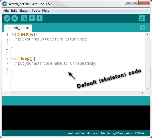
You can in fact compile and upload this code to the Arduino, but it won’t do anything. To make it blink the LED, we need a couple more lines of code. The first one, which will appear above all the rest, may be this:
byte ledPin = 7;
I know, almost all the other Blink tutorials on the web say something different (e.g. “#define LED_PIN 13”). Believe me, for our purposes it doesn’t really matter. Anyway, what this line does is create a value (the number 7), stored within a variable called “ledPin” of type “byte”, which will serve us throughout the rest of the code. While this is not strictly necessary – we could simply write “7” wherever we want – it’s a good practice because it makes subsequent changes really easy.
Now, let’s enter the curly braces of “setup()”. Whatever we write there will run only once, at the beginning – when the Arduino is powered or reset. So let’s tell it that pin #7 is going to be an output pin:
byte ledPin = 7;
void setup() {
  // put your setup code here, to run once:
  pinMode(ledPin, OUTPUT);
}
Any pin defined as “OUTPUT” can take either of two values: “LOW”, which connects it internally to GND we met earlier, or “HIGH” which connects it to 5V. These connections are not “hard wired” and should be handled with care. I only used this description as a rough beginner guideline.
We want to turn on the LED, but we also want to turn it off later, and repeat that process again and again. So we’ll write the relevant commands inside the curly braces of “loop()”, where – as the name suggests – they will run in a loop until power out or reset.
void loop() {
  // put your main code here, to run repeatedly:
  digitalWrite(ledPin, HIGH);
  digitalWrite(ledPin, LOW);
}
Note the specific letter case, the commas, parentheses and semicolons. These are essential elements of the programming language and if you mess with them, you’ll get errors and bugs.
If you run the above code, it will appear as if the LED is always on. That’s because microcontrollers are really fast, and each command we wrote is executed within a millionth of a second, give or take. Our eyes are definitely not sensitive enough to register such fast blinking; we have to slow it down. For that, after each state change of the LED pin, we’ll put a delay command. This function accepts as a parameter the number of milliseconds to do nothing. Here’s the complete Blink code, minus the now-unneeded comments:
byte ledPin = 7;
void setup() {
pinMode(ledPin, OUTPUT);
}
void loop() {
digitalWrite(ledPin, HIGH);
delay(1000);
digitalWrite(ledPin, LOW);
delay(1000);
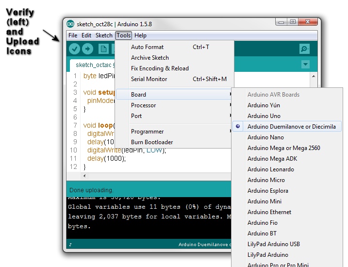
}You can verify this code by clicking the “Verify” icon with the check mark at the top left of the IDE. This compiles the codes and notifies you of any syntax errors in it. If no issues are found, it’ll simply say “Done compiling.”
We’re almost ready to upload – we just need to tell the IDE where to send the data. From the Tools->Board menu, pick the board model you have, and from Tools->Port select whatever option is there; assuming you only have one Arduino connected and no other esoteric equipment, there should be only one.
Now, click the “Upload” icon, with the arrow. This will compile the code again (yep, no trust) and then attempt to upload the compiled result to the Arduino board. If everything goes right, some lights on the Arduino board itself will blink fast for a couple of seconds (that’s the uploading process, not your Blink) and finally your LED will go on an off in all its glory, at one second intervals.
Congratulations. Now let’s move on to the interesting stuff.
P.S. Do you still remember what the Anode is? Try this mnemonic: “Anode” is reminiscent of “Another”, and Another is like More, or Plus. Therefore, you’d usually connect the Anode to the Plus, the positive voltage.