
I finished the 595 Beginner’s Guide with a fairly simple example project. As a supplement, here’s another project, based on the same setup but just a little bit more complex, where we manipulate another input pin on the IC – and by doing that, control the output LED brightness!
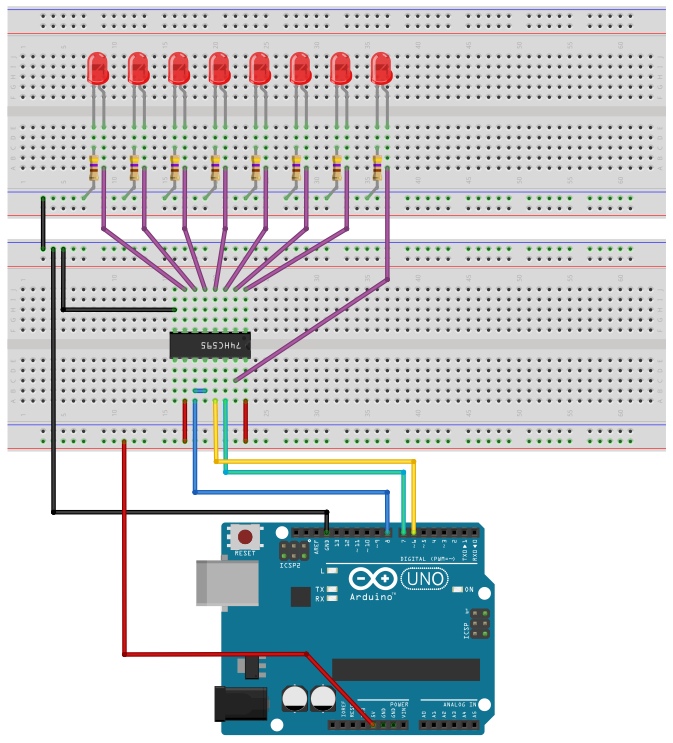
As you can see in the drawing above, the only physical change from the previous project is that I removed the connection from pin OE to GND and replaced it with a connection to Arduino pin #6 (yellow wire). I chose pin 6 because it’s one of the PWM pins – the pins through which the microcontroller can produce Pulse Width Modulated signals (i.e. “square waves” of alternating HIGH and LOW voltages at about 500Hz frequency, with selectable ratio of HIGH to LOW on each cycle).
The Arduino code is similar to the previous one as well, except here the light pattern we’ll be producing is not random (it will be just on/off/on/off…), and we’ll also feed different PWM signals into pin 6 of the Arduino. The HIGH parts of the PWM signal will cause the OE pin to temporarily disable (it works with negative logic, remember?) all the IC outputs. This will happen, of course, faster than our eyes can perceive directly, but we will definitely sense a variation in the overall brightness.
const byte intensity[8] = {254, 250, 245, 238, 230, 216, 180, 0};

const byte SER_PIN = 7;
const byte SRCLK_PIN = 8;
const byte OE_PIN = 6;

void setup() {

pinMode(SER_PIN, OUTPUT);
pinMode(SRCLK_PIN, OUTPUT);
pinMode(OE_PIN, OUTPUT);

byte n = 0;

void loop() {

analogWrite(OE_PIN, intensity[n++]);
if (n == 8) n = 0;

digitalWrite(SRCLK_PIN, LOW);
digitalWrite(SER_PIN, !n);
digitalWrite(SRCLK_PIN, HIGH);
delay(60);

}
The values in the intensity array were chosen to create a more-or-less linear change is perceived brightness. If you don’t see this change, dim the lights in the room or look at the LEDs from the side.
Nice simple tutorial. I found your blog while refreshing my memory on how to use a 595. I’ve just now managed to daisy chain a 299 and two 595s – destined to become an EEPROM writer and reader. Your other posts are great too. Talking of the evil of libraries – I wasn’t satisfied until I had an ATmega328 on a breadboard, flashing a LED, and talking via USART only using code I had written. I use libraries but I like to know how to do it myself. I will have to try an ATtiny85 with a slooooow clock. 🙂
Hey, Great tutorials.
Could you make a tutorial about 555 timer?
How does it work and how can you use it?
Thanks!
All in good time 🙂
But I think the 555 is so common and popular, there should be lots of good resources out there already.