
The auto-off function of most powerbanks is a pain in the neck for makers, who want to use these devices as power sources for systems with low current demands. Here’s how I overcame the problem with one of my old powerbanks.
Disclaimer: Not all powerbanks are created equal, and the solution shown here may not work – or may cause serious damage – in other models. Also, sloppy handling may cause short circuits with very grim consequences, and the warranty is obviously void once you open up the powerbank. You’ve been warned…
The high capacity and the convenience of powerbanks would have made them ideal for maker projects, but for one caveat: the auto-off function, which turns them off after a few seconds of low power consumption. For charging a phone, “low” would mean a few dozen milliamps, but that’s a lot more than many other systems need. For example, a home-made datalogger, or a remote-controlled robot waiting for commands, can require just a couple of milliamps over relatively long periods.
A non-intrusive solution would be to add an element to our system, that would consume short bursts of high current, at intervals of a few seconds. The exact current and interval required will vary according to the powerbank, but can be found easily with a little trial and error. However, adding such an element may not be a trivial task in all systems.
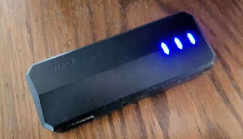
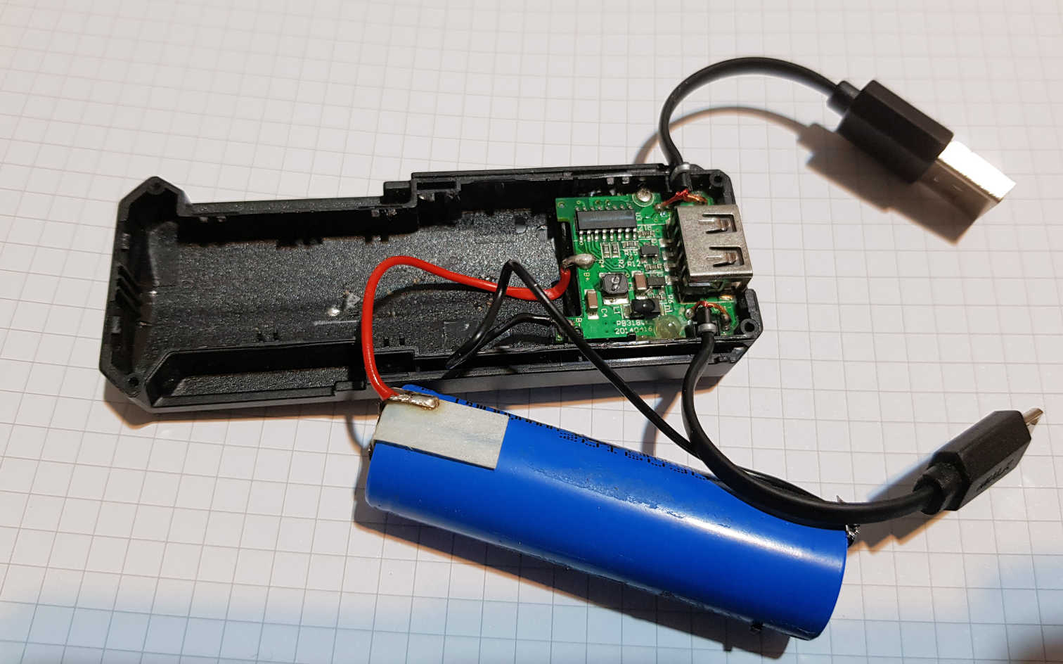
Another option, the dangerous one, is to open up the powerbank, find out what makes it shut down and neutralize that feature at the source. I took this as a challenge with an old powerbank of mine, that contains a single 18650 battery and has a manual on/off switch.
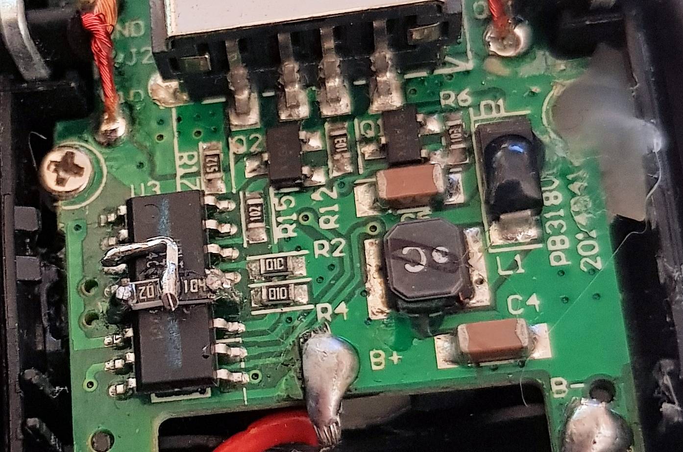
The major IC, seen in the picture above, is a Holtek HT64R064B. Turns out it’s a cheap, generic One-Time-Programming microcontroller; this is the “brain” of the powerbank, and it seemed reasonable that it decides when to turn the power supply off. But based on what?
After chasing a little red herring, which to save your time I will not detail here, I turned to the four analog input pins of the MCU and tested the voltage on each one, under different loads. I discovered one of them was used to test the voltage of the inner battery itself. Two others had stable voltages (probably not used by the firmware), and the last one had small voltages, in the order of millivolts, directly proportional to the loads. Where did this information come from?
Turning the PCB over, I noticed two salient things: an IC marked AP5058 (the charging manager, which is irrelevant to the outgoing currents), and a relatively large piece of black foam with holes, which protected the status indication LEDs. Beneath that black foam was the missing link: a 1206-sized resistor marked R050, i.e. 0.05 Ohms. That is a current sense resistor: the current goes through it and, as Ohm’s law teaches, some voltage is necessarily dropped on it. But since it’s such a small value, the voltage drop is very small. Small enough not to matter for the power output, but still large enough to measure (especially since this MCU has a relatively high-resolution ADC, 12 bits).
I ran the numbers from my aforementioned measurements with this new information and it fit. Pin 3 of the MCU was getting a reading from the current sense resistor. Now what?
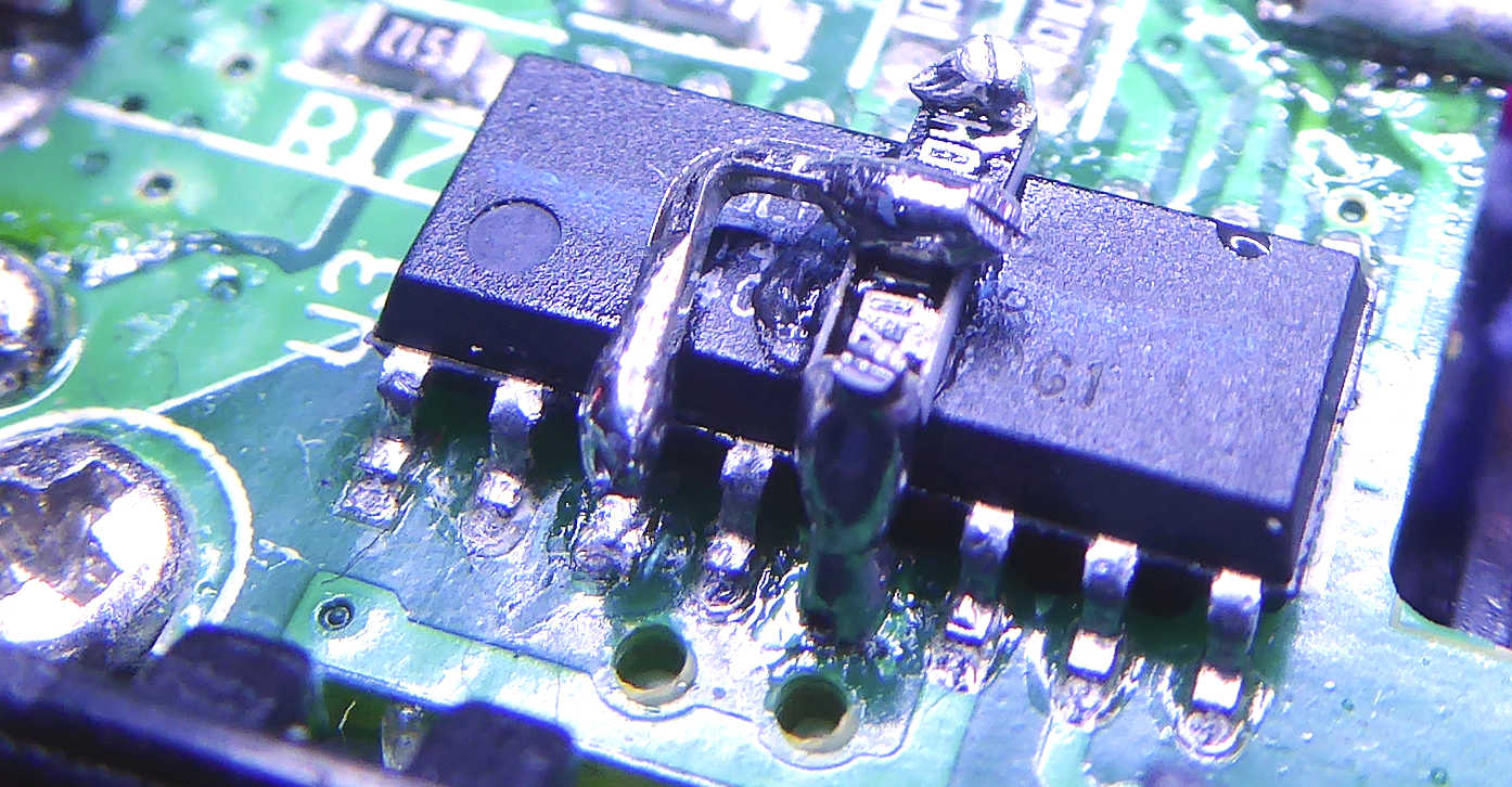
Fortunately, the MCU had a SOIC package, which is big enough to manipulate with a soldering iron and tweezers. I pulled pin 3 gently from its pad and bent it a bit upwards. Now, floating pins (in this case, literally floating!) can sense all kinds of unpredictable voltages, but for science’s sake I turned the powerbank on. It always turned itself off after a single second, no matter what load I attached. Bingo!
My collected data showed that 10mV on pin 3 is enough to keep the powerbank operating. What will happen if I give it an unreasonably high voltage (such as the MCU’s operating voltage, which can never come out of that current sense resistor under normal circumstances)? Will the firmware panic? I wasn’t sure I wanted to know – I’ve been lucky enough not to ruin anything so far – so instead I glued and soldered two 0805 resistors, values 100KOhm and 1KOhm, to the back of the MCU and to its Vdd and GND. These resistors serve as a voltage divider whose output provides pin 3 with constant 38mV – equivalent to about 0.5A load.
…And it worked! Now the powerbank can be turned on and off only with its pushbutton. It will stay on even with nothing connected, probably until it drains its own power on the internal ICs and LEDs.
i am looking for power bank auto on/off 5 volt
Do you have this type of thing?
Auto on/off 5V? Isn’t that almost every power bank on the market?
Very nice
wonder if i can pick your brains on a simular but different problem , mine is not a problem of low current draw on my load, mine is that my power bank will switch/on off. when i plug it into a charger. i want to basically keep my load on 24×7. when i am out on battery only. then come home plug the battery in to charge n keep load going. (it’s a small enough. load for the charger) darn thing cycles on/off. when i either plug into charger or even unplug from charger. any ideas. how i might. resolve this??
Good question, with a disappointing answer: the circuits in most powerbanks really can’t handle that kind of setup, and there’s no reasonable hack that I know of. If anyone knows a way, I’d love to hear it too!
If a power bank (without a trickle charge mode) has more than one output, could one connect one of the outputs to the device that only draws low current for charging (which if connected by itself would lead to the power bank shutting off within a few seconds), and the other output to something like a cell phone or other device that draws more current for charging. The second device would keep the power bank “on”. Would that then allow the first device (that draws only low current) to be charged?
That, as my thesis supervisor used to say, is an empirical question 🙂 So I put it to an empirical test now, using a very cheap power bank with two outputs. When only one was used, to power an Arduino board, it shut down quickly. When the other output was used simultaneously to charge a phone, the Arduino kept on going. So, at least for that particular simple power bank, the answer is yes. But of course, it’s a rather wasteful method.
Can you please add more clear image from both side of IC. I got the idea but I did not understand clearly.
Added at the end of the post, that’s the best angle I can get… but of course it will only be useful if you have *the exact same* IC in your device.
Remember that pin 3 is physically disconnected from its pad on the PCB, and lifted up to meet the bent lead on the top.
Did you remove the current sense resistor?
No, I just re-routed the MCU pin that read the voltage drop on it.
Very nice read, thanks for sharing! Powerbanks are indeed very helpful for small projects – I recall once putting one into a radio-controlled airplane to have an Arduino on board. 🙂