
In this guide I will introduce the cheap and useful IC (Integrated Circuit) nicknamed “595” – a Serial-to-Parallel chip, which is commonly used as an output port expander for Arduino and other MCU projects.
Introduction
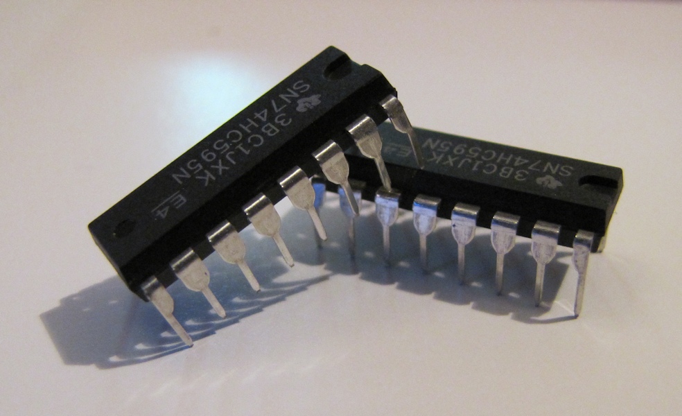
A favorite among beginner Makers, the 595 essentially outputs, on eight separate output pins, the last eight inputs it received through a single input pin. The 595 comes in a variety of makes and models; here I will talk about the ubiquitous Texas Instruments SN74HC595N. If you get a different one, read its datasheet carefully and make note of any differences.
Pin Mapping
Here’s the drawing of the 595 chip from the datasheet, with an explanation for every pin. Notice that two pins have a line over their name; this means they operate in “negative logic”. You can ignore that for now.
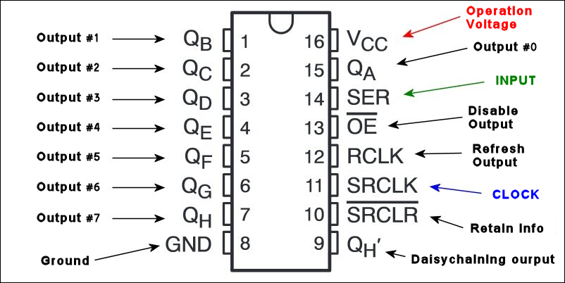
Notice the U-shaped marking at the top of the chip in this drawing. There’s an actual mark like that on the real IC (see photo at the top of the post). This will help you identify the pin locations. Before you connect anything, make absolutely sure the chip is aligned correctly.
Functional And Pin Description
The 595 has two registers (which can be thought of as “memory containers”), each with just 8 bits of data. The first one is called the Shift Register. The Shift Register lies deep within the IC circuits, quietly accepting input. To see what it stores, we have to copy its contents into the second register, the Storage Register. Each bit of the Storage Register is connected to one of the output pins QA–QH of the IC, so in general, when the value in the Storage Register changes, so do the outputs.
Here are the “commands” at our disposal when using the 595:
Writing to the Shift Register is accomplished with two pins: the Serial Input pin (called SER) and the Shift Register Clock pin (SRCLK). Whenever we change the voltage on SRCLK from low/GND to high, two things happen:
- The bits in the Shift Register move one step to the left: Bit 7 accepts the value that was previously in bit 6, bit 6 gets the value of bit 5 etc.
- Bit 0 in the Shift Register accepts the current value on SER.
The SRCLR pin allows us to reset the entire Shift Register, making all its bits 0, at once. This is a negative logic pin, so to perform (or maintain) this reset we need to set the SRCLR pin low. When no reset is required, this pin should be high (Vcc).
To copy the values in the Shift Register to the Storage Register, change the voltage on RCLK pin from low to high.
Pin OE means “Output Enable“, and it’s negative logic too: When the voltage on it is high, the output pins are disabled – set to high impedance state and don’t allow current to flow. When OE gets low voltage, the output pins work normally.
Pin QH‘ (note the quote mark, “Prime”) outputs bit 7 of the Shift Register. It is there so that we may daisychain 595s: if you connect this QH‘ to the SER pin of another 595, and give both ICs the same clock signal, they will behave like a single IC with 16 outputs. Of course, this technique is not limited to two ICs – you can daisychain as many as you like, if you have enough power for all of them.
Example: Random Bits
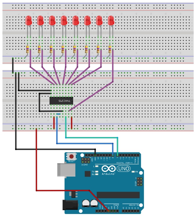
In this small project, we attach an LED to each of the 595’s output pins, and make random lights “run” along the row of LEDs with commands from an Arduino.
Step 1: Connections
– Connect the 595 Vcc pin to the Arduino 5V pin, and the GND pin to any of the Arduino’s GND pins.
– Get 8 LEDs, arrange in a row and connect the anode of each (the long leg) to the appropriate output pin of the 595 (see illustration below). The cathode of each LED should be connected through a 470 Ohm resistor (or higher) to GND.
– Connect OE to GND, so that it won’t disable the output.
– Connect SRCLR to Vcc, so that it doesn’t reset the Shift Register.
– Connect SER to pin 7 of the Arduino, and SRCLK to pin 8.
– For simplicity’s sake, we’ll connect RCLK directly to SRCLK. When both rise from low to high at the exact same time, the Shift Register is copied to the Storage Register first, and only then it gets updated with the new input.
Here’s the drawing. Notice where the U-shaped mark is, and don’t forget to connect RCLK to SRCLK (here, the short blue wire):
Step 2: Arduino code
The main loop in the following code is very simple: 1) Make the clock signal low, 2) Set a random voltage (high or low) on the SER pin, and 3) Raise the clock signal to activate the 595 updating process.
const byte SER_PIN = 7;
const byte SRCLK_PIN = 8;

void setup() {
  pinMode(SER_PIN, OUTPUT);
  pinMode(SRCLK_PIN, OUTPUT);
}

void loop() {

  digitalWrite(SRCLK_PIN, LOW);
  digitalWrite(SER_PIN, random(2));
  digitalWrite(SRCLK_PIN, HIGH);
  delay(200);

}
If you did everything right, you will see a random, infinite pattern of on/off lights moving along the row of LEDs at a leisurely pace.
Things To Watch Out For
The 595 pins can source (“give”) current. or sink (“take”) it. However, there’s no way of using them as inputs. The actual amount of current each output pin can provide is quite low, perhaps about 6-7mA max. Make sure you protect the 595 outputs from higher currents using appropriate resistors and/or other components.
This IC can work at a Vcc of 2-6V, and the Vcc is of course the upper limit for the high voltage on any output. However, high outputs may be a bit lower than Vcc, and low outputs may be a bit higher than GND. Vcc also dictates the highest clock frequency that the IC can handle, starting at 5MHz for 2V. At 4.5V, it’s already 25MHz – more than the regular Arduino can provide anyway.
Now What?
This information is enough to get you working with the 595. Add to the example above a separate control of RCLK, and with three output pins from the Arduino you can have precise control over as many outputs as you like. The price of this expansion is, of course, the time it takes to update the ICs; but in many cases, that’s a price you can afford. Any questions? That’s what comments here are for 🙂
Update: Another example project
Update 2: If you don’t feel like doing all the coding yourself, you may want to check out Timo Denk’s convenient 74HC595 Shift Register library for the Arduino,
I can’t make this circuit work as drawn. Instead I seem to need to add pull up resistors to the QA–QH output pins in order to get the LED’s to light up. When I add these I get the LED’s turning on and off when I expect them to.
Adding a pull-up to an *output* pin is an odd concept (it means the LED is fed from the pull-up when it’s on)… unless you made some mistake in the circuit, it means your 595 is some rare model that has open-drain output – check the exact model number.
Hi ,
thanks for the tutorial , it was clear and easy to understand and i did the connections to the 595 ic and it worked as expected … at least until i disconnected the Vcc …
even when i disconnected the vcc from the breadboard the led was still on … it’s strange
what can be the cause of this ?
As far as I know, many ICs have a certain internal protection from over-voltage on their I/O pins. When Vcc is disconnected, any positive voltage is over-voltage… so some currents flows through the I/O pins to GND, and the chip may seem to be working. Of course, in this mode it is extremely unreliable and unpredictable.
You mention that the pins can either source or sink current. How do you wire it up so that it the active pins go to ground or act as current sinks?
When an output pin is High, it can source current; when it’s Low, it can sink current. Just like a digital output pin on an Arduino.
Nice intro to the 595.
Different vendors sometimes label the pins differently, for example NXP has MR instead of SRCLR. The pinouts are always identical though.
I have a bunch of Ti PDIP parts, and find they will output ~9mA @3V with a 3V3 supply. That works great for blue LEDs without current limiting resistors.
Thanks!
Nice example. Do you know how to make running LEDs with slowly fade out?
looking for your reply.
Thank you.
Thanks. To add a fade effect (which essentially goes “on top” of the light pattern) you have to alternate between “LEDs ON” and “LEDs OFF” so quickly that the eye will not notice the blinking, and gradually increase the OFF time. The OE pin is ideal for this control, but you’ll have to write the logic that operates it. One option is to use variable PWM (available in every modern MCU), another is to write your own routine that will count time and bit-bang the ON-time and OFF-time. Note also that this will effect ALL the LEDs; with the 595 it’ll be quite difficult to dim only certain LEDs convincingly!