
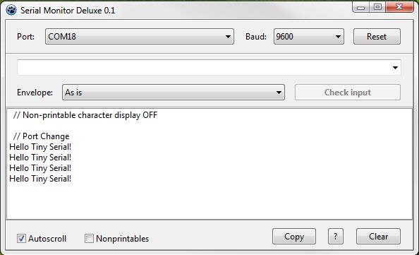
How Arduino’s Serial transmissions are constructed, and a basic demonstration of the ATtiny85 sending Serial-like messages using an internal timer and some basic bit manipulation.
The Motivation
The Arduino Serial class is a very useful tool for communication and basic debugging, because it allows us to send focused, detailed information in a comfortable format that we can also easily save and manipulate on the PC.
When moving from Arduino to smaller, weaker MCUs that don’t have the appropriate hardware support, Serial is definitely missing. However, if you can spare one hardware timer and one I/O pin, you can form and send data in the correct format, to be picked up by any serial-capable device: Arduinos, USB-to-UART modules (such as those used to program Arduino Pro Mini boards) etc.
Structure of a Serial Byte
For simplicity’s sake, Iet’s talk about Arduino’s most common serial setup, also known as 9600,8,N,1. This means 9600 bits per second, 8 bits (1 byte) in each data unit, No parity bit (an extra bit that could help us detect errors), and 1 Stop bit to signal the end of a data unit.
The 9600 bits-per-second rate (“Baud”) means that each bit occupies 1/9600 of a second, or 104.17 microseconds. Armed with this information, let’s look at an actual Serial transmission from an Arduino. First, here’s the code:
void setup() {
  Serial.begin(9600);
}

void loop() {
   Serial.write(202); // Binary 11001010
   Serial.write(105); // Binary 01101001
   delay(2000);
}
I chose these values because their bit patterns should be easy to spot and unambiguous. Here’s what the logic analyzer got from the TX pin:
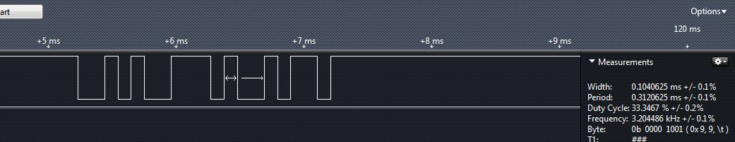
Note that when the line is idle, it’s actually in HIGH state (5V). The shortest discernible unit here, marked with the double-sided arrow, is about 104.06 microseconds long (see text on the right), which is very close to our calculation, and probably well within the measurement error. This is, then, a single bit. Let’s use its width as a reference to mark all the bits in this transmission:
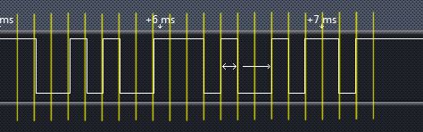
It’s quite easy to tell where our numbers are – as soon as we realize that they were send in reverse, i.e. Least Significant Bit (LSB) first. Each number begins with a “Start bit” (0V, as a contrast to the idle state), then our 8 bits, then the Stop bit that brings the line back to HIGH.
Recreating TX on the ATtiny – Overview
We have now three tasks to accomplish. The first is to tune some clock, or rather a metronome, to the correct bit-rate. Then, we’ll build on that to send a single byte with the appropriate “frame”. The third task would be to send whole strings. If you really want to, you can go even further to sending numbers as formatted strings, but that’s beyond our current scope. What I describe here can obviously be accomplished on any AVR, or any reasonable MCU for that matter; Here I’m using the sweet little ATtiny85.
Step 1: The Metronome
Let’s say we have the Tiny’s clock set to the internal oscillator at 16MHz. To get 1/9600 sec “tick” we need a tick once per 1667 clock cycles (rounded). The Tiny’s timers are 8-bit, so they can only go as high as 255. We have to use a Prescaler to “slow them down”.
I chose to use Timer0, which has a limited selection of prescaler options. Out of these, I chose the one that gives the result closest to a whole number: Clk/64. This gives us 1667 / 64 = 26 (rounded). I’ll set the top limit for Timer0’s counter to 26; each time the counter will reach this value, it’ll cause an interrupt and restart counting. We’ll use this interrupt’s service routine (ISR) to toggle an output pin, and see what signal we get. Here’s the code:
#include <avr/io.h>
#include <avr/interrupt.h>
int main(void) {
// Define pin PB0 as output
DDRB = 1 << PB0;
// Set top value for Timer/Counter0
OCR0A = 26;
// Basic CTC (Clear Timer on Compare) mode
TCCR0A = 1 << WGM01;
// Set Timer0 prescaler to clk/64
TCCR0B = (1 << CS01) | 1 << (CS00);
// Activate timer0 A-match interrupt
TIMSK = 1 << OCIE0A;
// Enable interrupts
sei();
while(1) ;
}
// Timer0 A-match interrupt
ISR(TIMER0_COMPA_vect) {
// Toggle output on PB0
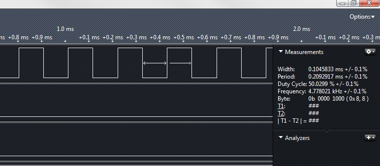
PORTB ^= (1 << PB0);
}And here’s the output. Bingo!
Step 2: A Whole Byte
Let’s do this in an orderly fashion. We’ll create a record with the byte to send, and the number of bits left to send (including the frame bits). This record will be populated by a dedicated function, and used by the ISR.
We’ll also want to turn off the interrupt once it finished its work; so we want to be able to restart it, too. Don’t forget to reset the timer counter when starting a transmission, otherwise it may reach the top limit too soon and the Start bit will be too short.
Here’s a partial code – just the new important parts:
volatile struct {
  uint8_t dataByte;
  uint8_t bitsLeft;
} txData = {0, 0};


void sendBySerial(const uint8_t data) {
  txData.dataByte = data;
  txData.bitsLeft = 10;
  // Reset counter
  TCNT0 = 0;
  // Activate timer0 A-match interrupt
  TIMSK = 1 << OCIE0A;
} // sendBySerial


// Timer 0 A-match interrupt
ISR(TIMER0_COMPA_vect) {

  uint8_t bitVal;

  switch (txData.bitsLeft) {

    case 10: bitVal = 0; break; // Start bit
    case  1: bitVal = 1; break; // Stop bit
    // Next option: transmission end
    case  0: TIMSK &= ~(1 << OCIE0A); return;

    default: // Data bit
      bitVal = txData.dataByte & 1;
      txData.dataByte >>= 1;
  } // switch

  // Set pin to appropriate output
  if (bitVal) PORTB |= (1 << PB0);
   else PORTB &= ~(1 << PB0);
  --txData.bitsLeft;
}
This works, so let’s move right on to…
Step 3: Strings
We can take two approaches to sending strings. We can either incorporate the whole thing into the interrupt service routine, or wrap the existing code with a simple function that evokes the byte-sending function for each character in the string. The second approach is blocking, meaning it will stop the running of the “usual” code until the transmission is complete. That could be a disadvantage or an advantage, depending on the specific system. Again, for simplicity, I’ll take the blocking approach.
One thing to remember, though, is that the byte-sending process is non-blocking; it runs almost in the background. So if we wish to send several bytes, we need to know when each byte transmission was finished. We could simply check whether the timer A-match interrupt is disabled, but that may be too implementation-specific. It’s safer to have an explicit flag that will be raised by the transmitting process.
In the final code, I also added a way to select which pin serves for transmission (“TX”). It’s very simple with the ATtiny85 that only has one pin port. For bigger MCUs, the code will be a bit more complex.
Code is here: http://pastebin.com/cKn6G2mL
When compiled, in takes a bit less than 5% of the Flash and SRAM of the chip. Connect the TX pin to the RX pin of an Arduino, or to a USB-to-UART adapter, join their GND pins to have a correct voltage reference, and enjoy your outgoing Serial! 🙂
Hi,
very nice and useful code I like to ask you what modifications needed to work also at 1Mhz and 8Mhz
Thanks in advance,
Kyriakos
Basically you only need to re-adjust the timer prescaler and the timer limit (OCR0A) per the system clock. However, note that at 1MHz, the number of processing cycles you have available between bit transmissions is getting low, so you have to watch your code carefully.