
Auto on/off, responsive, power-saving, and you get to select the threshold and to decide the exact nature of the feedback: Here’s how I built a convenient continuity tester from simple components and a cheap 8-pin PIC microcontroller.
Maybe three out of four times I reach for a multimeter, it’s only for testing continuity. It means turning the multimeter on, setting it to the correct mode (a couple of clicks or a careful turn of a dial), then turning it off again afterwards so that it doesn’t waste battery or frighten me with reminder beeps. A simpler, dedicated device could make life easier.
There are plenty of DIY continuity tester circuits and projects out there. Many of them are essentially nothing more than a battery in an open circuit, that gets closed through the probes and lights up an LED or activates an active buzzer. While this technique certainly works, it has two drawbacks. First, you don’t have a clear threshold. Does a bright LED mean zero Ohms resistance or 500 Ohms? If the LED looks dim, is it because the resistance is 3K Ohms, or because the room is lit up better? Second, we fallible humans can’t always make a perfect, continuous contact with the probes, so the device might shine its LED for, say, 30ms to let us know there’s continuity, but we just blinked and missed it.
So I sat down and wrote my wish list for a dedicated device:
- Lightweight, compact
- Clear, known threshold (determinable? even better)
- Clear light & sound feedback
- No buttons or dials – fully automatic, silent on and off
Let’s start with the last item. Today, everyone will probably think of a capacitive touch sensor. Some years ago, perhaps a mechanical vibration sensor would jump to mind as a way to determine when the user intends to use the device. But I thought, what’s the first thing we do when we pick up a continuity tester? Make contact between the probes, of course, to verify that it works. So why not use that – the closing of the circuit itself – to wake the device up?
That can be achieved easily using an “external interrupt” of a microcontroller. Just set the interrupt to “Rising edge”, pull the interrupt pin to GND using a high-Ohm resistor, and let the probes bring it to contact with V. Until that happens, the MCU can stay in a deep sleep mode and consume almost no current. This scheme does not help with the second item in my wish list, but that can be solved when the MCU wakes up. Instead of giving feedback immediately, it can take an analog, ADC measurement from the very same pin. Knowing the aforementioned resistor’s value, we essentially have a voltage divider and can determine, to the extent of the ADC’s resolution and accuracy, the resistance between the probes!
It is important to note that the external interrupt has a relatively lenient threshold (defined by what the MCU perceives as “HIGH” digital input), so the minimum wake-up resistance will always be higher than the maximum “this is continuity” resistance by any practical definition.
I chose Microchip’s PIC12F1572 microcontroller for the job. It has a small, Maker-friendly PDIP-8 package, and it’s relatively simple and cheap. If the firmware decides that the resistance is less than 100 Ohms (this can be easily adjusted in the code) it gives a predetermined feedback: for about 0.3 seconds it blinks a white LED and outputs a 4KHz square wave (from the internal PWM module) to drive a buzzer – many buzzers are loudest and most noticeable at this frequency. At the end of the feedback phase, the MCU tests the resistance again. If it’s still low, the cycle repeats. Otherwise, the MCU goes back to sleep. Note that if the resistance oscillates somehow, this might mean that we’ll only get feedback once; but such a situation should be extremely rare, and anyway the code can be easily fixed to deal with it (I leave it to you to think how it can be done).
My first breadboard-based prototype functioned well, but the sleep current was too high: 26uA. None of the usual suspects (floating pins, peripherals left active needlessly etc.) was found guilty. For over an hour I tested increasingly obscure theories in an attempt to figure out what had happened. Eventually I replaced the MCU itself with another one from the same batch. The current consumption dropped immediately to the expected 0.2uA. I can only assume that the first MCU got zapped by an ESD or a short circuit while I was preparing my circuit.

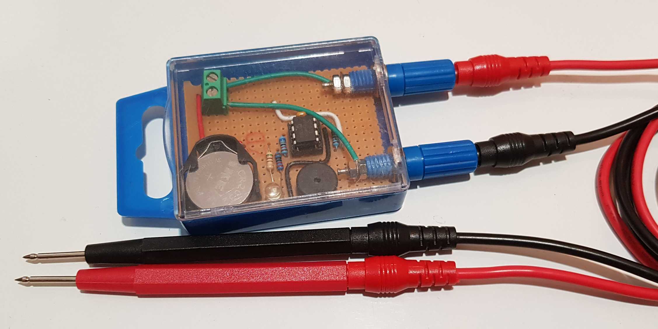
The build itself was straightforward. I found a little box and fitted it with two banana plug posts, for multimeter probes. The programmed MCU was fitted in a socket, soldered to a protoboard together with the LED, buzzer and required resistors, and a CR2032 battery holder. This battery’s 3V and low capacity is still more than enough for years of reasonable operation, now that the sleep current is to spec.
You can check out the firmware code – it’s mostly just writes to registers to set things up. It was written for the XC8 compiler (v2.32) in MPLAB X v5.5 IDE.
Please show the schematic diagram of the device.
Sorry, I don’t have one – I improvised. But you can decipher most of it by looking at the image at the top of the post (click it for a larger version)